Killing the wire rat's nest
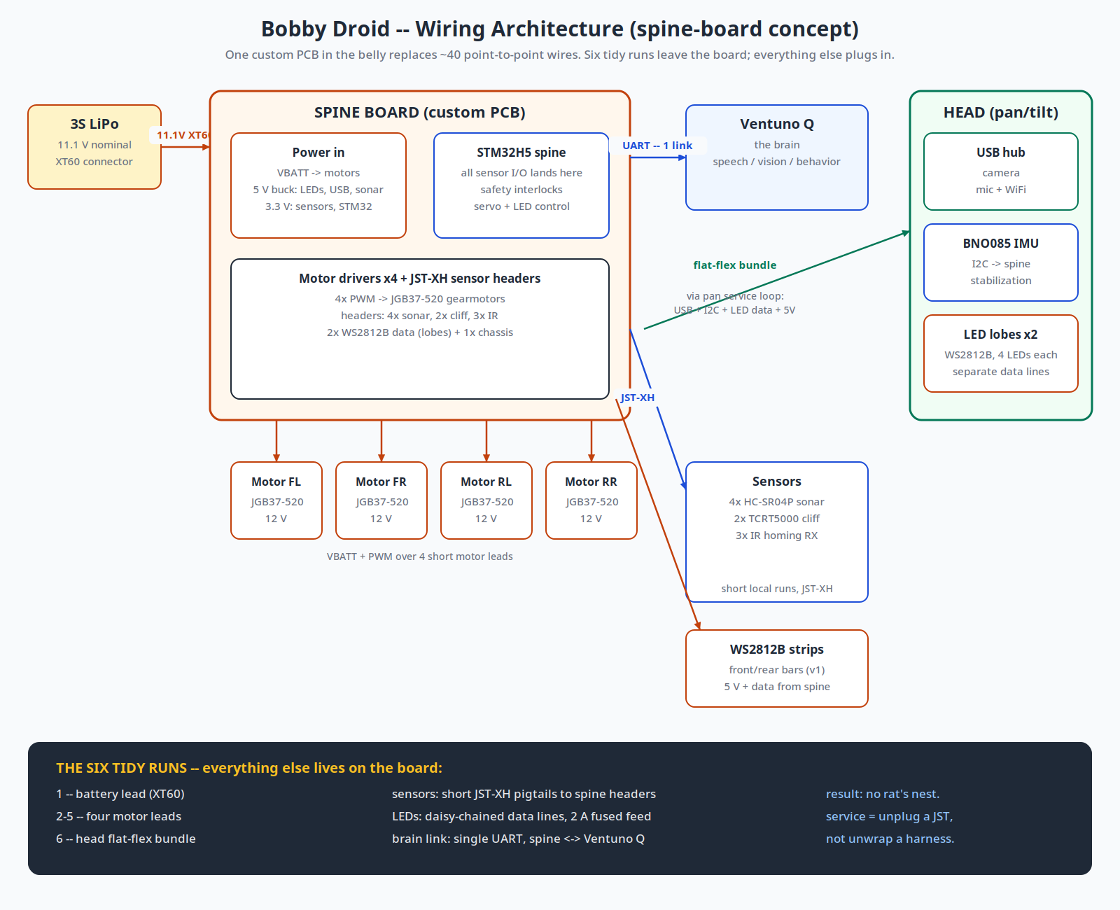
Every Raspberry Pi and Arduino project ends the same way: a hairball of jumper wires. Aircraft-style hand-built harnesses help, but they're bulky by design — built for airframes, not robots. The real fix isn't a better harness. It's fewer wires.
The answer is a custom spine board: one PCB in the droid's belly that takes the battery in and hands out fused 12 V, 5 V, and 3.3 V rails, carries the STM32H5, the four motor drivers, and JST-XH headers for every sensor. Five boards cost less than a pizza.
Six tidy runs
With the spine as the wiring concentrator, only six runs leave the board: the battery lead, four motor leads, and one flat-flex head bundle through the pan service loop. Everything else is a short plug-in pigtail. Servicing means unplugging a JST — not unwrapping a harness.
WIRING DISCIPLINE
| Connectors | Crimped JST-XH, keyed and locking — no DuPont jumpers |
| Wire | Silicone-insulated: thinner, flexible, doesn't fight back |
| Pan joint | Flat-flex ribbon in the service loop (loves single-axis bends) |
| LEDs | Daisy-chained data, 2 A fused feed, 40% brightness cap |
It turns out this is the same philosophy as the Bluetooth headsets built back in the day: modules on boards, board-to-board interconnects, zero flying wires. Just with more room to work.
← Back to the build log