
The Indrustic router base: a stacking shoe for flush cuts
The cut
The staircase trim needs one cut done over and over: a flush cut, with the router riding on two reference planes — the stair tread support and the riser support. A stock trim-router base is small, tippy, and blind for this kind of work. So instead of fighting the tool, the shop builds a shoe for it.
The concept: a pin-registered stack
Quick and dirty, on purpose. Three kinds of plate, one idea — two alignment pins locate everything:
Base shoe (bottom). This is the part that touches the work. It rides the tread support and the riser support, and off to one side it has a receiver area with two alignment pin holes.
Router shoe (top). The router bolts to this plate, and two alignment pins on its underside drop into the base shoe's receiver. The router rides on top of the stack; the work references stay on the bottom.
Riser plates (middle). When the cut needs the router higher than its own depth adjustment can reach, stack riser plates between the two shoes. Every plate carries the same two-pin pattern — pins on the bottom, holes on the top — so the stack daisy-chains and the bit stays over the cut line no matter how tall it gets. Make each plate a round number thick (12 mm, say) and "two plates" becomes a known, repeatable height instead of a guess.
The router
The motor is a Craftsman CMCW400 Type 1 — V20 brushless compact router, 1/4" collet, fixed base with both macro and micro depth adjust. That last detail simplifies the whole jig: coarse height comes from the plate stack, fine height from the router's own micro-adjust. No lead screw, no knurled knob, no second mechanism to build. The jig does one job; the router keeps doing its job.
Mounting is a straight screw-on: the stock sub-base comes off and the router shoe takes its place using the same screw holes. That keeps the bit concentric and the factory depth adjustment working exactly as designed. A clamp ring around the motor body would work, but it risks slipping and throws away the depth rack — screws win.
Three things the design has to respect
Pin fit is everything. Two pins give location plus anti-rotation — but only if the fit is honest. PETG doesn't hold tight tolerances, so the holes get modeled 0.2–0.3 mm oversize versus the pins, and a little pin-and-hole test coupon gets printed before any full plate. A wobbly stack ruins the whole idea.
Mind the cantilever. The router hangs off to one side of the receiver while the base shoe is what's touching the supports. Keep the bit as close to the reference planes as the cut allows, and give the base shoe a generous footprint on the support side — stability geometry is a feature, not an accident.
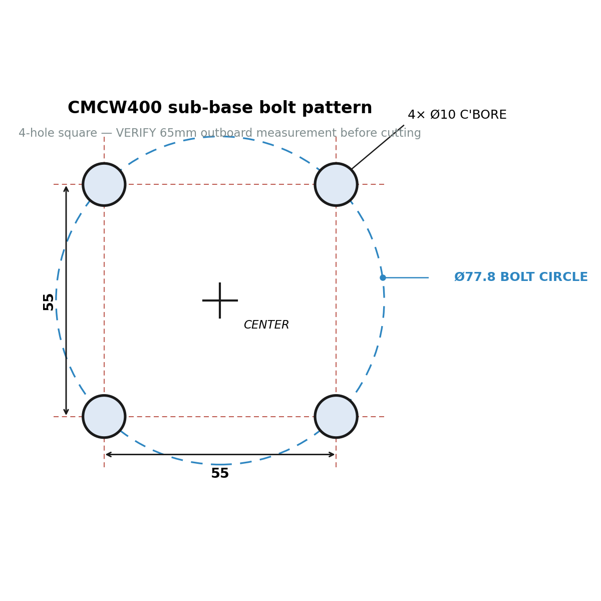
Measure the pattern twice. The sub-base bolt pattern is taken from caliper readings off the stock plate: 65 mm outboard-edge to outboard-edge across Ø10 mm counterbores, which corrects to a 55 mm square (not 60 — the first pass subtracted one radius instead of two). Center hole lands 27.5 mm off each centerline; bolt circle is Ø77.8 mm. It gets re-measured fresh before anything is cut — the reliable trick is calipering same-edge to same-edge, where the reading is center-to-center with no subtraction at all.
Materials and roadmap
Version 1 is 3D-printed PETG — ribs instead of mass, and steel or brass only where something actually rubs. Machined aluminum stays on the roadmap for later, if the printed version earns it. The budget is nonexistent; the ambition isn't.
Design files
Every tooling article ships its drawings. Download what's here; STLs, STEP files, and the Fusion model land in this section as the design matures.
Download bolt-pattern diagram (PNG)
DESIGN FILES
| Bolt-pattern diagram | PNG, dimensioned — 55 mm square, Ø10 mm c'bores, Ø77.8 mm bolt circle (unverified) |
| Shoe plate STLs | Pending — base shoe, riser plate, router shoe |
| 3D model | Pending — Fusion 360 source |